 |
 |
|
|||


|
|||||
|
|
|||||
|
|||||||||||||||||
How to use NP National Pipe Gages With Some Do's & Don'ts of NPT & NPTF NPSM & NPSF Thread Gages
How to Use a National Pipe Gage Basics
Which face of the NPT NPTF or ANPT Ring is Marked ?
Are there separate Go & No Gages for NPT Threads?
NPTF / NPT So what is the difference?
NPTF / NPT Thread Crest Checking?
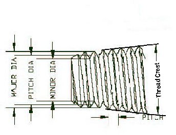
TERMS & DEFINITIONS (You may not have known this many variations existed)
RULE OF ENGAGEMENT FOR THREAD GAGES
CARE & FEEDING of
THREAD GAGES
OOPS!
I DROPPED MY THREAD GAGE
IS THE THREAD RING
WORN OUT?
Below are a few
simple explanations and general guidelines to the use of NPT (National
Pipe Taper) thread gages. As always when in doubt refer to the
ANSI/ASME referenced specifications like ASME B1.20.1 and B 1.20.5 & B1.20.3 which you can
obtain through the ASME web site(
http://www.asme.org/).
We've
purposely tried to keep
the explanations simple
so remember, if this is not enough information, especially for the NPTF threads,
go to ASME and get the full specification. Note: the information provided here is
only a
simplified general representation for using thread gages and is not meant to
replace or conflict with any published standards established by formal
organizations such as NIST, ANSI-ASME or your own internal ISO and quality
procedures. Always consult the governing specifications for complete accurate
details that you should use when working with thread gages to inspect your
parts.
Remember that a thread ring or thread plug is an Attribute Inspection not a quantitative type of inspection. The only possible outcome of using an attribute thread gage is pass or fail. Attribute inspection is
inspecting the product at the very limits of the tolerance band. It can not actually measure and quantify the specific pitch diameter
or taper of a thread. Attribute Inspection is not an acceptable SPC method of inspection.
HOW TO USE a NATIONAL PIPE GAGE BASICS
Using National Pipe Gages (NPT, NPTF, NPS) is really pretty simple, if the Go thread plug for NPS (straight) goes in to the threaded hole and the NoGo does not then the product is usually considered within the tolerance limits and acceptable. Using the NPT or NPTF or ANPT gages can also be simple since you only have 1 primary L1 gage that acts as both Go and NoGo using the gauge notch(s) or ring face to line up with the end of the product thread +/_ the allowable tolerance the basic thread form is within compliance. Of course with NPTF and ANPT the complexity increases when the L2/L3 is called for to determine compliance to a wrench tight position and thread taper.
WORK PLUG or WORK RING
is exactly that, a
thread gage used to check your products. It is not a setting plug , master plug
or master ring, Those are used to check the NP style work plugs & rings to make sure
they are in compliance.
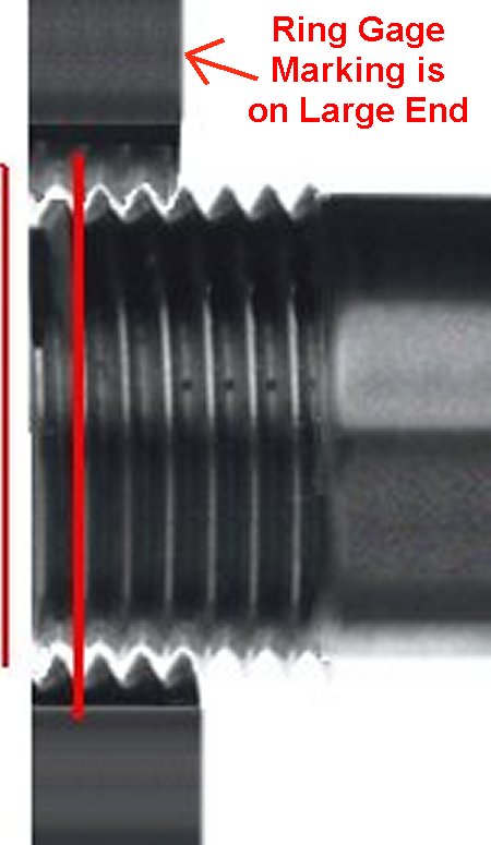
Which End of the NPT,NPTF & ANPT thread ring is UP? I hate to admit it but this does come up occasionally. Of course the BIG end is facing the product which is usually obvious. But the real question being asked is which end of the Thread Ring is marked. ASME specifically states in section B 1.20.5 for NPTF that the Thread Ring is marked on the face of the large end. B1.20.2 for NPT does not make that distinction but, and this is possibly and area where we use the word ASSUME which we all know can get us in trouble, almost all Thread Gage OEMs will carry the NPTF marking convention over to the NPTF gages. I want to be careful here because there will always be exceptions that find the marking on the back face or on both faces or if specified by the customer on the small end face. Because ASME B1.20.1 does not require this marking convention today, you may find variations so when in doubt look at the gage or measure the minor ID if you can, which hopefully will provide a clue as to which end is small and which end is large.
NPT/NPTF differences are due to the fact that NPTF is used as a Dry Seal (no pipe dope or Teflon tape used between the two mating threads) while NPT requires some sort of sealing medium to prevent leaks.
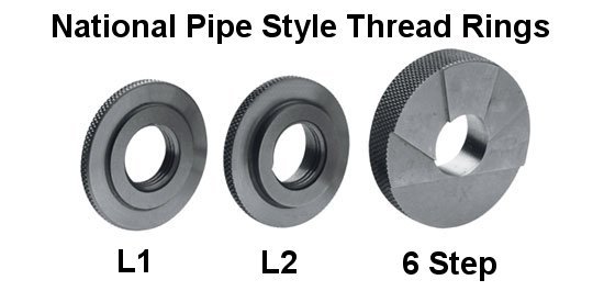
With NP threads, both tapered and straight, for Fuel and oil (NPTF or NPSF) as described in B1.20.5 & 1.20.3, conformance to the L1, L2 and L3 function may not be sufficient to assure that the threads will Dry Seal. In addition to the normal functional inspection these gages provide, you need to insure the thread crest and root truncations are held on both mating products. The plain 6 step plug or ring can be used to confirm that the thread crest is within specification. In Class 2 threads the L1 L2/L3 as well as the 6 step crest inspection is required.
NPTF may also require L1 / L2 in Basic or in 3 step and or 4 step configuration, based on the requirements placed by the user for the checks performed. As we recommend, you will definitely want to have a copy of ASME B1.20.5 and 1.20.3 on hand to reference for NPTF thread requirements.
We have had several requests and questions concerning the availability of either the L2 or L3 depending on if plug or ring as well as a six step to check the NPT threaded part. Let me start with NO! But then make some qualifying comments. There are no recognized L2 or L3 or 6 step gages for NPT threads. The reason is that NPT threads are used with a sealing component like Teflon tape or pipe dope that makes up the leak proof seal. The NPT thread is more forgiving of the wrench tight check that is required on NPTF (dry seal) and the taper or crest check is again not specified. The statement for taper is that it is "Assumed that the supplier will check his tooling thereby confirming conformity for the taper attribute"
No you can not effectively use the L2 or L3 NPTF gage to check the NPT threads even if it is specified that the wrench tight (L2/L3) conformity or the taper (six step) attribute needs confirmed. If you do require an additional inspection, you can only use the ANPT L2/L3 gages and six step for this application. The ANPT is made with the same PD values of the NPT thread form. thus will effectively work to check this L2/L3 feature.
There are not separate Go and No-Go gages to confirm that the product is within the specifications allowable.
Yes we know there are exceptions to this statement.
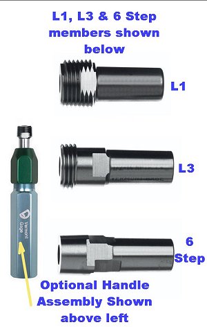
NPTF THREAD CREST CHECKING: NPTF gages have more critical crest tolerances so are commonly inspected with a smooth 6 step plug or ring. The 3 sets of steps ( please refer to the photo below), are used in conjunction with the NPT L1 which is used first to establish if your product is at nominal, max or minimum tolerance. Once you establish that your product is, lets say nominal (perfect), you then would use the middle sets of notches in the 6 step to judge whether your crest (and taper of the crest) is within the two notches. You will do the same if the L1 shows the product at the high or low limit of this gage using the high or low set of limit notches in the 6 step plug.
NPT THREAD CREST CHECKING: NPT threads normally do not require checking the thread crests since these crests are not as critical in the sealing of the male and female products. NPT uses sealing mediums like Teflon tape to create a leak proof seal. However if required due to special requirements or concern that the crests are truncated a special ANPT (Aeronautical NPT) 3 step gage can be used. The tolerances for the ANPT 3 step is correct to check your NPT thread crest and taper compliance.
You will always be required to use the L1 first to establish the reference for this thread compliance.
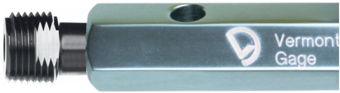
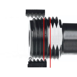
The photo shown is a typical L1 NPT Thread gage plug assembly. Notice the notch in the plug which is used as the depth indication associated with a nominal ( Basic) internal thread in your product. In this example the plug is screwed into (clean please) internal threads and is considered in compliance when this notch is within +/- 1 full turn of being flush with the starting point of the threads being measured. Below is a depiction of a thread plug inserted into a part showing the general acceptable upper and lower limits. Keep in mind you have + 1 and - 1 full turn on the threads for the L1 hand tight plug or ring. Rings are flush with the small end of the thread ring gage or plugs should be flush with the last thread and the notch in the gage plug. There can be exceptions but generally this is the inspection method. As always when in doubt consult ASME specifications ( http://www.asme.org/) or any special applicable requirements for your particular requirements.
Thread Plug
For Internal Threads
Thread Ring Shown on External Threads
Lets start with a few of the basic
terms you may encounter:
NPT NPSC
NPTR NPSM NPSL NPSH
ANPT
NPTF-1
NPTF-2
PTF-SAE short
NPSF
NPSI
The letters have very specific
meanings as follows (N= National (American) Standard, P= Pipe, T=Taper)
C= Coupling, S= Straight,
M=Mechanical, L=Locknut, H=Hose Coupling, R= Rail Fittings. A=Aeronautical
F= Fuel & Oil, I= Intermediate
TERMS & DEFINITIONS (You
may not have known this many variations existed)
A= Aeronautical
Note this
specification is in compliance with Mil-7501.
We will stick with the more common
types, if you need more information consult ANSI/ASME B1.20.1
NPT: is a pressure tight thread
form which is used with a sealing agent like a Teflon tape or other compound
like pipe dope to create the seal between the male and female threads.
NPTF: thread form is a pressure
tight thread that is called Dry Seal and does not require any special sealant
material be used. It depends on the interference between the truncated thread
crests and thread root of the mating products to create a mechanical seal (See ANSI B1.20.3 for inch and B1.20.4 for metric
translation).
L1: Is a gaging member that
effectively checks the functional conformance of the threads. The L1 by
definition, is threaded into or on the threaded portion of the product until
L2 ( Rings) or L3 (Plugs) are
terms you will find that refer to a second inspection required on these threads. This
inspection is performed using the L2 or L3
Note: we find this inspection is normally associated with NPTF (Dry
Seal) style threads so do not get confused if you are dealing with just standard
NPT. Not to say that your customer will not require the same sort of inspection
but it is rare on NPT.
6 Step plain ring or plug
normally is a requirement of the Class 2 NPTF thread or if called out in the
thread specifications.
The plug and ring are used to make a Thread Crest inspection of the product.
The use of this plug can be a simple inspection related to the Basic L1 thread
gage but may also be more complex based on the classification of the thread if
at the Minimum or maximum condition. The steps used on this plain gage change
based on this condition. For more detailed information please consult ASME
B1.20.5.
Class1
NPTF, PTF-SAE Short (external) require the coordinated use of both the L1 & L2 gage rings.
NPTF, PTF-SAE, Short (internal) require the coordinated use of both the L1 & L3 gage plugs.
NPSF, NPSI require inspection with
the L1 gage.
Class 2
Back
to the top of the page
 Go
Back to the Store
Go
Back to the Store
RULE # 1 through 10 "If it does not fit DON'T FORCE IT!" Back
to the top of the page
Back to the top of the page
FIRST RULE OF ENGAGEMENT: Thread Gages are NOT!
?Thread Chasing devices
?Lapping Or Re-Sizing Tools
?De-burring Tools
?Used to Measure Actual Size?
?Hammers (don't laugh its been done!)
?Thread Cleaning devices
CARE &
FEEDING of THREAD GAGES
?Never force a Gage into or on a Part Being Checked
?Handle gages as you would any precision tool
?Misuse or mishandling can result in nicks or other deformities which can destroy the integrity of the gage
?Store gages in a secure location, preferably in individual compartments or containers
?Gages should be dipped in an oil-wax based seal or coated with a rust preventive prior to storing
?If you must ship gages, pack them separately, coated with rust preventive, with sufficient packing material to avoid
damage.
OOPS! I DROPPED MY THREAD GAGE
So you have used the gage to inspect a lot of parts and have concerns if the gage is worn or has been
damaged! Lets take this issue logically and break it down into two basic functions which are geared towards, first, a Thread Plug gage and second a Thread Ring gage.
When your Thread Plug gage was originally manufactured the OEM had the luxury of having an entire quality department set up to
measure the gages and confirm that they were in compliance with the prevailing standards and checking methods. If you are like most users you probably did not
anticipate having
to replicate their quality department.
%$#@!. Thread gages will wear out, they will get dropped or stored in such a way as to cause
damage on the very surfaces you
are depending on to qualify your products. As such you should always have back
up gages on hand and be prepared to replace your gages periodically.
How do you do a quick, seat of the pants, confirmation after dropping the gage or finding out that you are all of a sudden rejecting everything you are making
(or maybe worse yet passing everything a little too easily)?
If you prepare a little in advance, you can make a quick confirmation if the gage is seriously damaged
(or not) by saving one or two of the original parts you passed (or did not pass)
when you first received the gage. Remember this is not a substitute for a
correctly certified master! You might consider keeping one or two parts around that
originally passed & failed if possible just for this type of sanity check.
NO, DO NOT GO TO THE LOCAL HARDWARE STORE AND USE ONE OF THEIR PARTS AS A REFERENCE,
THERE ARE NO ASSURANCES THAT THOSE PARTS ARE CORRECT!
Second if you are making and inspecting threaded components you should
make preparations to periodically inspect your plugs for wear and damage. The
simplest method to periodically check your gage for wear and and damage is to
have a master plug or ring gage. Worn
or damaged thread gages need to be replaced! Your parts
are not much good to your bottom line if they are sent back due to
nonconformance issues.
It is very strongly recommended that you purchase the master plug with
your thread gage.
Back to the top of the page
IS THE NPT THREAD GAGE WORN OUT?
Tapered Plugs and Rings can really only be checked for excessive wear using a special master Plug or Ring. If you depend on these gages to qualify your products, you should always have a master Ring (of course for the Thread work plug) or a Master Thread plug (for the working thread ring). Gages wear out with use so always have a spare and if this is an important part of your production you should have a master(s) to audit your thread gage periodically.
Go Back to the Web Store
NOTICE: All information provided on this reference sheet is intended to be for general guidelines and may not represent the full
specifications or instructions as outlined within ASME requirements or other technical specifications which govern the manufacturing and use of thread measuring gages.
thegagestore.com/LEECO INC, does not represent this information as anything
except a common sense general set of guidelines. You must always follow
the technical specifications relative to the gage, thread design or
other related gage attributes and usage that apply. When in doubt always acquire
the current specification from
http://www.asme.org/ codes & standards.
IF YOU
HAVE QUESTIONS OR COMMENTS, E-MAIL
Technical@thegagestore.com
OR FAX US AT 860-404-8903
![]()
![]()
![]()
![]()
![]()
![]()
![]()
Copyright © 2001-2017 All Rights Reserved
Read
our security and privacy polices
E-Commerce Designed and Hosted by
SYO Computer
Engineering Services, Inc.
![]()