 |
 |
|
|||


|
|||||
|
|
|||||
|
|||||||||||||||||
FAQs
ABOUT UN (UNS, UNEF,UNJ, UNF, ect.) & METRIC THREAD GAGES
How to Set Your Thread Ring on Youtube
How To Use Thread Gages (UN, UNJ and Metric styles)
Basics of Using Go & No/Go Plugs & Rings
The
Secrets of UNJ Thread
Gages No One Ever Told You (MIL-S-8879 Superseded by
SAE-AS8879)
RULE OF ENGAGEMENT FOR THREAD GAGES
CARE & FEEDING of
THREAD GAGES
TERMS & DEFINITIONS
CHOOSING THE RIGHT THREAD PLUG STYLE & HANDLE
IS IT A STANDARD OR
SPECIAL THREAD GAGE
TAPS & DIES WHAT IS ALL THIS H1, L1, H2 ect. ect.
The Plain Truth About
Chrome Plating Thickness
OOPS! I DROPPED MY THREAD GAGE
Is My Thread Gage Worn Out?
THREAD RINGS ARE A HORSE OF ANOTHER
COLOR
Adjusting a THREAD RING GAGE to a TRUNCATED
SETTING PLUG
Do I Really Need That Special Setting Plug for My Thread Ring (YES and YES)
IS THE THREAD RING WORN OUT?
The Plain Truth About
Chrome Plating Thickness
A WORD ABOUT METRIC
MY TWO THREAD GAGES DO NOT CORRELATE:
HOW CAN MY NOGO GAGE GO IN (ON) MY PART BUT MY GO GAGE WILL NOT!!!!!
INSPECTION OF PLASTIC, NYLON & SOFT
MATERIAL THREADED PARTS
I'M
DESPERATE FOR MORE DETAILS WHERE CAN I GET THEM
You will find simple instructions and answers to FAQs we have compiled regarding the care and use of thread plugs, thread rings, setting masters for thread rings
which apply to UN (Unified Thread 60
degree inch) and Metric 60 degree thread forms, and other full form thread gaging products.
We have tried to keep the explanations simple and easy to understand in the hope that we can help our customers understand the
care and use of thread gages for
measuring threaded products. Note: the information provided here is only a
simplified general representation for using thread gages and is not meant to
replace or conflict with any published standards established by formal
organizations such as NIST, ASME or your own internal ISO and quality
procedures. Always consult the governing specifications for complete accurate
details that you should use when working with thread gages to inspect your
parts.
Remember that a thread ring or thread plug is an Attribute Inspection not a quantitative type of inspection. The only possible outcome of using an attribute thread gage is pass or fail. Attribute inspection is
inspecting the product at the very limits of the tolerance band. Go and NoGo Ring and Plug Gages are the most common type screw thread inspection devices and usually act as a functional inspection not only of the PD but offer a full
engagement of the thread form with the gaging member. It can not actually measure and quantify the specific pitch diameter of a thread. Attribute Inspection is not an acceptable SPC method of inspection.
Basic use of
Go/NoGo Thread Plugs & Rings
Using thread gages is really pretty simple if the Go thread plug goes in to the threaded hole and the NoGo does not then the product is usually considered within the tolerance limits and acceptable. The inverse is true of rings. Questions arise in some areas of how to judge if the product is not good using the NoGo gage. The specifications state that the product can be acceptable if the No Go thread ring engages the end threads of the product being tested but should not thread over more than 3 (three) complete turns on the product. Do not force the gage on to the product and on thin walled parts, be especially aware that the gage may be more easily forced into or over the product distorting the product.
The Real Truth about UNJ Thread Gages
Thread gages, using designations
UNJ, UNJC, UNJF, UNJEF are made to a specific requirement as referenced in such
specifications as Mil-S-8879
SAE-AS8879 and ASME 1.3 - 2007 & B1.15 - 1995 for the
Aerospace, Military & Government applications. If you are making threads that
use these designations you will need gages that are also designated with the J
to signify that your gage is in compliance. Reference changes to MIL-S-8879 go
to SPECS ON THREAD GAGES page listed in the Home Menu.
Now the simple truths, (as always we recommend that you acquire the relevant specifications for all the facts), Go and NoGo gage plugs, used to inspect internal threads, must be specifically marked confirming that they are in compliance with the applicable standards so that you will pass an audit that requires this specific thread gaging.
Thread rings for external threads are more complex. All J designated thread rings must also be marked but they must be made with a rounded root radius not the standard 60 degree V as with normal UN style gages. This requirement is referenced in the product specification B1.15 - 1995 and the Thread Gage specification B1.3 - 2007. Specifically the product specifications, B1.15 - 1995 Unified Inch Screw Threads, (UNJ Thread Form) specifies the characteristics of the UNJ inch series of threads having 0.15011P to 0.18042P designed radius at the root of the external thread, (Thread Rings for checking these external threads must also comply), and also having the minor diameter of the external and internal threads increased above the ASME B1.1 UN and UNR thread forms to accommodate the external thread maximum root radius.
As always you can obtain relevant specifications at http://www.asme.org/ .
RULE # 1 through 10 "If it does not fit DON'T FORCE IT!"
Back Home
Depending on your requirements a special (Custom) thread gage will be
manufactured to your special requirements. Just let us know at
Technical@thegagestore.com .
The Plain Truth About Chrome Plating Thickness
Does it really pay to have thicker Chrome plating or not? When it comes to
Thread Plug Gages the answer is really
Thread rings will require that you use a special Thread Setting Plug made
specifically for that thread size or a super micrometer with all the
balls, pins and calibration software required for this type of inspection.
We are
always being asked how long will a thread gage wear and the answer is we just
can not predict. Every possible variable, changes even an educated guess. Materials
like cast iron or even coarse grained aluminum wear these gages prematurely even
when chrome plated. The actual number of parts tested, the cleanliness of the
thread when testing it and the tightness of the gage to part all have an impact
on the certifiable life of these gages.
When in doubt, get
them recertified or at the very least ,set up some sort of method to confirm
that the gage is still within the allowances permitted. If you want a reasonable
method to confirm that the thread plugs used on UN and Metric threads are valid
and not worn beyond tolerances you might use the three wire measurement method.
This method is pretty basic and can be implemented in even small shops to verify
the thread plugs. The method is described fully in ASME B1.2 but primarily you
will take three specially sized wires called "Best Size" with a measuring
instrument ( most likely a digital micrometer) with 0.000010 inch resolution and
having contact tips of sufficient size to span two of the wires comfortably
when making a measurement of the Pitch Diameter. If you are going to set up
this method to help your compliance to your ISO procedures we recommend that you
obtain this specification from ASME in order to completely understand it.
Below we have inserted a graphic with the normal formula you can use for this
measurement. Remember this method can be subjective depending on the micrometer
you use and pressures on the wires but it certainly is a great way to determine
of your thread plug is worn out between official calibration checks. If done
carefully it can also act as a calibration verification for used gage plugs.
Before you do this, make sure you have the ASME specification and follow their
recommendations completely! This is only an example of how you can verify your
gage is still in tolerance at the pitch diameter but this method does not verify
other features of the gage so always consider what your needs are before
assuming one test is all inclusive. This method is not meant to replace any
official certification method on thread gages.
without marking. Alternate the use to spread the wear evenly to the
entire Thread Ring to prolong
the life of the gage.
NO NO NO
FIRST RULE OF ENGAGEMENT: Thread Gages are NOT!
•Thread Chasing devices
•Lapping Or Re-Sizing Tools
•De-burring Tools
•Used to Measure Actual Size•
•Hammers (don't laugh its been done!)
•Thread Cleaning devices
CARE &
FEEDING of THREAD GAGES
•Never force a Gage into or on a Part Being Checked
•Handle gages as you would any precision tool
•Misuse or mishandling can result in nicks or other deformities which can destroy the integrity of the gage
•Store gages in a secure location, preferably in individual compartments or containers
•Gages should be dipped in an oil-wax based seal or coated with a rust preventive prior to storing
•If you must ship gages, pack them separately, coated with rust preventive, with sufficient packing material to avoid damage.
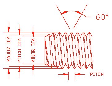
TERMS & DEFINITIONS
A 60 degree thread plug is shown below
UN - unified screw thread constant pitch series
UNC - unified screw thread coarse pitch series
UNF - unified screw thread fine pitch series
UNEF - unified screw thread extra fine pitch series
UNJ - unified screw thread constant pitch series, with rounded root
on external threads & Thread Ring Gage
UNJC - unified screw thread coarse pitch series, rounded root
on external threads
& Thread Ring Gage
UNS - unified screw thread Special diameter, pitch or length of engagement
UNJF - unified screw thread fine pitch series, rounded root
on external threads
& Thread Ring Gage
UNJEF - unified screw thread extra fine pitch series, rounded root
on external
threads & Thread Ring Gage
M - Metric Screw Threads- M profile with basic ISO 68 profile
MJ - Metric Screw Threads- MJ profile with rounded root
on external threads
& Thread Ring Gage
MJS - Metric Screw Threads- MJ profile profile special series
on external threads
& Thread Ring Gage
There are many more definitions for other thread types including National Pipe which we cover in the special section
"HOW TO USE NPT and other NP style gages, dedicated to those thread forms.
For more detailed information you can obtain the Screw Thread Specifications B1.7M 1984, directly from ASME via their web site.
Back Home
 Go
Directly to the Store
Go
Directly to the Store
Confused about the different handle and styles of Thread Plugs?
Handle Styles can make a difference. Below you will see the two standard handle types of handles, Taper Lock and double ended reversible.
We always prefer and recommend the Taper Lock Style on thread plugs over the
Double Ended Reversible Style, because the tapered stub fits into a tapered recess in the handle
providing more surface contact between handle and thread plug member which holds the thread plug member firmly resisting rotation in the handle.
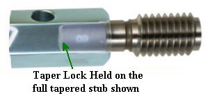
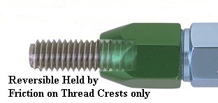
TAPER LOCK STYLE DOUBLE ENDED REVERSIBLE STYLE
Remember if your thread plug slips in the handle first check your product
to see that the thread
PD, Lead and root diameter (major) is correct, that the entry thread is not the
problem, or if the threads are not
clean. If these are okay, review your gage style to make sure it has enough
friction holding the gage member tightly for the application.
Back Home
IS IT A STANDARD OR SPECIAL THREAD GAGE?
QUESTION:
Is the gage called out with a "S" in the notation like UNS or MJS?
Do you have a non-standard Pitch Diameter called for?
If you are unsure, we have provided a PDF sheet for each ring and each plug
within the store site that will let you open and print the "Pitch Diameter
Reference Chart". You can either select your product category, subcategory and
product size at the store site or click this reference here to see the PDF chart
for standard sizes. To see
a typical PD chart you can go back to the front page and click on the "Tolerance
Chart" button in the center of the page.
Does the gage require special treatment such as a UNJ with rounded root radius?
Are you measuring the part before a plating operation "Pre-Plated" that
requires a custom thread PD?
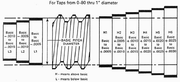
TAPS & DIES, HOW DOES THE TAP CLASS CHANGE THE
PDs?
What PD is generated by your tap operation? See the Tap class
example below. Remember these classes of taps determine the PD sizes they will
cut. You will need to specify the PD of the gages you need based on your
experience and these target sizes before a gage OEM can manufacture your
specific thread gage.
Note: We do not provide advice on taps and machining processes, you should consult your local expert if ever in doubt.
Back Home
OOPS! I DROPPED MY THREAD GAGE
So you have used the gage to inspect a lot of parts and have concerns if the gage is worn or has been
damaged! Lets take this issue logically and break it down into two basic functions which are geared towards, first, a Thread Plug gage and second a Thread Ring gage.
When your Thread Plug gage was originally manufactured the OEM had the luxury of having an entire quality department set up to
measure the gages and confirm that they were in compliance with the prevailing standards and checking methods. If you are like most users you probably did not prepare
to replicate their quality department.
%$#@!. Thread gages will wear out, they will get dropped or stored in such a way as to cause
damage on the very surfaces you
are depending on to qualify your products. As such you should always have back
up gages on hand and be prepared to replace your gages periodically.
How do you do a quick, seat of the pants, confirmation after dropping the gage or finding out that you are all of a sudden rejecting everything you are making
(or maybe worse yet passing everything a little too easily)?
If you prepare a little in advance, you can make a quick confirmation if the gage is seriously damaged
(or not) by saving one or two of the original parts you passed (or did not pass)
when you first received the gage.
You might consider keeping one or two parts around that
originally passed & failed if possible just for this type of sanity check.
NO, DO NOT GO TO THE LOCAL HARDWARE STORE AND USE ONE OF THEIR PARTS AS A REFERENCE!
Second if you are making and inspecting threaded components you should
make preparations to periodically inspect your plugs for wear and damage. Worn
or damaged thread gages need to be replaced! Your parts
are not much good to your bottom line if they are sent back due to
nonconformance issues.
A simple method to check if the thread plug is due
to be replaced from wear is the method shown below. This is a relatively simple
method to confirm the PD on a plug but a word of caution. If you do not have the
"Best Fit" thread wires for your exact thread PD your results may be invalid. A
small difference in the thread wire diameter can make a large difference in the
measured PD values due to chordal error as the thread wire contacts the PD
surface of the gage.
It is very strongly recommended that you purchase the setting plug with
your thread ring. We recommend that you purchase the setting plug 100% of the time
for any custom thread rings when you order the thread
ring. Rings can get dropped on the job site, jarred in shipment and may need to
be reset periodically, so consider the small investment for the setting plug as
insurance that your products are leaving your shop with confidence.
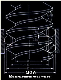
The picture shown
depicts the use of a micrometer and 3 thread wires used to establish the pitch
Diameter of a traditional 60 degree gage plug.
Back Home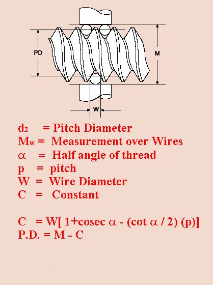
This is pretty simple and most of you experienced
thread heads know
these facts, but bear with me, since some of us have not had a lot of exposure to threaded parts and using thread rings to measure them.
First, as
most of you know, there are 2 (two) types of thread rings produced to measure the
functional fit of an external thread on a bolt or stud. You will still find the
occasional solid thread ring being used or called out but the predominant style
of ring in the USA is the split (or adjustable) thread ring. The exception is
for National Pipe rings to be explained in a different Technical section on the
site.
The split style of ring
was accepted many years ago by the regulating bodies as it became apparent that
solid ring costs both in manufacturing and end user durability were fast
becoming cost prohibitive. You can imagine what it might take to make a
"Perfect" thread form on the ID of a solid ring of steel cost
effectively, not to mention the potential scrap the OEM
could generate just to produce one saleable thread ring.
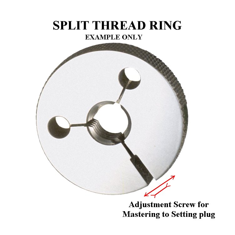
The split ring
however, which is most common for 60 degree thread forms, allows some small
amount of adjustment by the OEM, (and in special cases the end user or
calibration labs) based on a split adjustable design. This permits the OEM to
fine tune the ring to a SETTING PLUG. The setting plug lets the user do periodic checks of the ring
and determine if the it is time to replace the thread ring due to wear or
damage.
SOLID THREAD RING SHOWN
SPLIT RING
Back Home
THEY ARE NOT SUPPOSED TO FIT!!!
First lets explain. A work plug you use to inspect internal threads on your parts has a larger Pitch Diameter than the Pitch Diameter of a thread ring inspecting external threads on the mating part. Lets use an example shown below for 1/2" 20 2B Go Plug gage and a 1/2" 20 2A thread Go ring.
Work plug PD = .4675" The comparable Thread Ring PD is .4662" The larger work plug will not fit in your smaller work ring, no way no how! To check or adjust your thread ring you need a special setting plug specifically designed to check and readjust the thread ring gage. A comparable setting plug for the 1/2 20 2A ring will have a PD of .4662".
HOW TO USE THE
SETTING PLUG
We
will limit our explanation to the Truncated setting plugs we would normally
supply for standard and special 60 degree thread forms.
We use the term "truncated" to denote the leading threads of a special setting plug that has had the thread crests ground down as prescribed in standard ASME practices. In this example below we show the Full Form Thread and also the Truncated (ground down ) thread form.
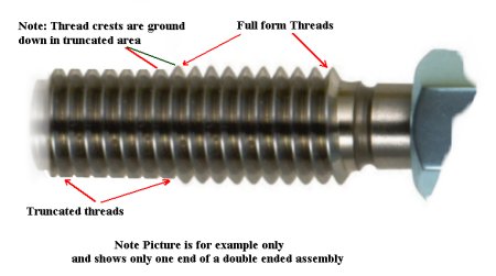
The reason to have 2 forms on this setting plug is to give the user the ability to check for wear on their thread ring both in the leading threads and also with full engagement. A procedure follows directly from the manufacture on setting your thread ring to the setting plug. The basics are as follows:
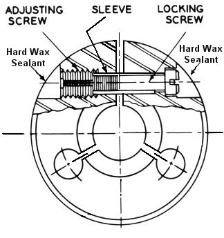
Now how do you actually set the thread ring to the setting plug? First of all you need to look at your thread ring and find the filled holes where the locking and adjusting screws are located. You will find in most cases two depressions that are filled usually with a hard wax. You can soften and remove the wax by gently heating it up but be careful not to put too much heat into the ring itself. We have used everything from a heat gun (very gently) to a soldering iron to soften the wax. Using a heat gun again do not heat the ring up too much and you can usually remove the wax plug cleanly. If you look at the picture below you will see the general configuration of most split thread rings. It consists of a locking screw (jam screw) and and adjusting screw that allows you to make small (SMALL) adjustments to fit the ring to the setting plug. After removing the wax let the ring sit to normalize to the ambient temperature again before adjusting it. If it is still warm your adjustment will not be correct once the ring cools down!
Adjusting a THREAD RING GAGE to a TRUNCATED SETTING PLUG
Make sure the setting plug being used is in good condition, proper PD not damaged or worn.
The following description will guide you to setting your split ring to the master setting Go or No/Go plug gage.
When the ring gage is set to the setting plug with uniform feel over the entire length of the plug, including no end thread shake, it is correctly mated with the plug. However, it is well to remember that because of tolerances in the manufacture of both the ring and the setting plug, and that unless they are made at the same time or ordered to be mated with each other, allowances must be made in the assembly feel or fit to compensate for slight differences. For instance, a slight difference in angle and/or Lead cause more of a tightening or drag at full engagement than over partial engagements. This is not a serious condition as both the ring and setting plug may well be within specifications.
If the ring gage is set to the truncated portion of the setting plug first instead of the reverse procedure described above, and it fails to pass over the first full thread of the full form section of the plug, there is major diameter interference in the ring and it should be replaced.IS A SETTING PLUG REALLY NECESSARY
Only if you want to verify the thread ring is not damaged and not pass reject parts or fail good parts
Unfortunately gages get dropped or can be damaged in shipment. Thread rings are more difficult to see that damage so the only practical way to verify that the gage is correct is to check it with a master setting plug
Only if you want to set more than 1 thread ring to the same setting standard and stop discussing which ring is correct
A common issue is that two thread rings are available usually one in the lab and one on the floor being used daily. Good idea but one basic problem is correlation. Fundamental tolerances of thread rings can allow several ten thousands of an inch in tolerance when the gages are adjusted to the OEM setting plugs. Couple that with the possibility that more than one setting plug was used when the thread ring was calibrated which also has a few ten thousands of an inch tolerance, plus the fact that the setting procedure used as outlined in ASME specifications has it's own "feel" when setting not to mention that the floor gage probably sees more product run through it so is worn a bit from when it was new and you have the problem.
Tolerance stack ups, wear, original setting plug used to calibrate rings if ordered at different times can lead to one ring passing parts while the other rejects them. Solution is to have your own setting ring that you use to adjust both thread rings to the same standard.
Only if you want to adjust your thread ring for normal wear and not pass reject parts or reject good parts
Lets talk about wear. A ring being used to inspect production parts is subject to all sorts of conditions. They are used to inspect threaded parts that are not clean, inspect parts with damaged threads, as thread chasing devices, as chip clean out devices and so on. As a result, wear is not predictable so you may never know if the gage is worn and needs readjusted to maintain the original tolerance you needed or in the event the ring is just plain worn out you will only know this when your customer rejects your parts or they fail in the field. Unless you have your own setting plug and follow a simple quality procedure to periodically check the thread rings and adjust or replace as needed.
YES the setting plug will pay off if you want to extend the life of the ring by adjusting it, do not want to pass bad parts or reject good parts because you were not aware of a damaged or severely worn thread gage.
Step 11 above will provide you an indication that the lead threads on your gage are worn but how do you check quickly if the entire thread form is worn and beyond adjusting range. Keep in mind that the adjusting screw is to "TWEAK" as we put it to make a very minor adjustment in the ring. This adjustment is not meant to change the PD of the ring to correspond to a custom undersized external thread nor to correct for excessive wear.
CAUTION: TRYING TO TIGHTEN THE RING ADJUSTING SCREW TOO MUCH WILL DISTORT THE RING CREATING AN INCORRECT FUNCTIONAL FIT EITHER PASSING NON-CONFORMING PARTS OR REJECTING PERFECTLY GOOD PRODUCTS.
A quick way to check if the ring is worn excessively is to use the truncated Setting Plug as follows.
1. Perform steps 4 & 5 above but thread the ring on only the truncated portion of the setting plug.
2. Perform steps 7 & 8 above until you achieve the "light drag" as required.
3. Now thread the ring the rest of the way over the Full Form threaded portion of the setting plug. You may feel a bit more drag but the ring should thread over the full form portion without any binding. DO NOT FORCE IT! If your ring is worn too much the ring will not easily screw onto the full form portion of the setting plug and needs to be replaced.
Even thought these rings are usually made of very hard material ( in some cases they are hard chrome plated) they do wear out so don't let yourself in for a customer reject, or worse yet, a field failure of the threads you have manufactured. Keep your gages in good condition check them periodically to make sure they are not worn beyond their wear limits, replace them when necessary.
ONE OF MY TWO Go RINGS or PLUGS PASSES THE PARTS BUT NOT THE OTHER ONE
Question; Can one Thread gage (Go) pass my part while another supposedly identical thread gage rejects it? ANSWER; YES, YES , YES!!!
WHY MY RINGS ARE DIFFERENT: There are multiple reasons that correlation issues can happen. To begin with, as an example, the setting plug used to set a thread ring with, has a tolerance on the PD of .0001"(usually) on a TPI count from 16 to 80 for thread diameters up to 1/2".
The larger the diameter the larger the allowable tolerance. Two setting plugs can be up to .0002" different from one another on PD alone so it is not unusual to find one gage will pass products while a second (Identical) gage will fail the part, when the parts are at one end of their tolerance or the other. If one of the gages has been used in production this issue is compounded by the wear of the lead threads and PD surfaces in the older gage.
SOLUTION: We strongly recommend purchasing a setting plug with the thread rings and having all the gages adjusted to the same setting master. Using the recognized procedures listed above for adjusting the thread rings, some 'FEEL" is used in the adjustment which contributes a small amount of additional differences between two rings set at different times to different setting master plugs by two different individuals.
WHY MY PLUGS ARE DIFFERENT: As with the thread rings above, tolerances must be considered in the manufacturing of the thread gage plugs. 32-80 TPI count gages up to 1 1/2" diameters have a tolerance of .0003"on their PD.
Armed with this knowledge it is easy to see how two (Identical) Go thread work plugs can have differences. One plug can theoretically be up to .0006" different in PDs from a second one therefore, not even considering wear, one can accept a part while the other rejects the same part when the parts are close to their lower tolerance.
SOLUTION: Understanding that this is the reality of attribute gages and that these gages wear, are dropped, and can have different PDs is the best solution. Check your certifications when you receive the gages, keep track of the gages and make sure you have a process to periodically check the gages for wear. You can also obtain an optional long form certification from the OEM that specifically provides the actual measurements of the PDs when it is manufactured so you can arbitrate these correlation questions with a little understanding of the potential issues.
HOW IN THE HECK CAN MY NoGo GAGE FIT MY PART BUT MY GO WILL NOT?
This situation can happen and is usually associated with using a single point tool to create the thread. You try the part with your Go gage and the gage will not go on, or in the case of an internal thread go in, your part. You pick up the NoGo gage and it will fit the part just fine. How can this be possible since we all know the Go Ring gage is larger than a NoGo ring and the Go Thread plug is smaller than the NoGo thread plug.
This is impossible unless the gages are wrong. Right? No, not always. If you have two situations that can easily be related to the machining process and tool wear you can actually encounter this situation.
First the tip of your tool breaks down which leaves the root of the thread shallow.
Second the tool is advanced to compensate for wear.
Resulting in the PD being oversized but with a shallow root of the thread.
The shallow root hits the crest of the Go thread gage stopping it from entering or going on the part even though the PD is oversized.
The oversized PD allows the NoGo gage to thread on (in) the part. Now you ask how can the NoGo thread on (in) the part if the root is shallow and stopped the Go gage.
ASME calls out a major diameter for the NoGo gage , both ring and plug to be smaller by approximately 25% from the Go gage.
The final result is that the oversized PD of the part will allow the NoGo gage to thread on (in) the part as long as the root is not shallower than this 25% offset of the major diameter on between the Go and NoGo gages.
The Plain Truth About Chrome Plating Thickness
Does it really pay to have thicker Chrome plating or not? When it comes to Thread Plug Gages the answer is really NO! As it pertains to Thread Rings there are some schools of thought that the extra thickness of chrome may allow you to adjust the ring more for wear but because the chrome plating is built up in the root of the thread some interference may be seen as the ring wears and you make adjustments. The real issue comes down to the fact the chrome thickness most OEMs plate the gages with is actually thicker than the allowable wear permitted for the gage so more is not always better.
A WORD ABOUT METRIC THREAD RINGS & PLUGS
The basics covered above apply to both UN and Metric thread plugs and rings. You will find that the typical classification call outs are different from the UN style but are similar. You will have classifications for Metric Thread Rings of 6g and 6g 4g which require a small difference in these two classes of rings. The Plugs are classed as 6H which also applies to the Thread Ring Setting plugs as well. Reference ASME B 1.16M for more complete information on metric thread gaging.
INSPECTION OF PLASTIC OR SOFT THREADS
Because parts made of plastic can be damaged more easily when threading a thread plug into internal threads or running a thread ring over external threads we usually like to advise users of the following trick. For right handed threads place the plug or ring at the entrance to the threaded part with light pressure and rotate the gage counterclockwise until you feel a small "click" as the lead thread on the part and lead thread on the gage just pass each other. This small click under light pressure tells you that you have almost perfectly lined the lead gage plug or ring thread with the entry point of the part thread. By doing this you limit the amount of surface the steel thread gage is run on the part before entering the threaded portion of the part. This method tends to help eliminate any scraping on the part due to misalignment. As always with steel gages on plastic parts, a light pressure is required in order not to "chase" the thread if it is undersized or damage lead threads by forcing the gage into the part.
Do not force the gage into the part. Plastic parts can be "Pushed" to allow entry of the gage which can seem to indicate that the part is the correct size. Also be particularly sensitive to any binding of the gage as your run it into or onto the threads since this may indicate ovality issues that can be of concern.
With Steel or hard material, any restriction will not conform to the thread gage so is easily detected while soft parts like plastics or nylon can conform to the gage or worse yet actually be chased with the steel thread gage giving a false indication of acceptability or create damage to the thread form. As always make sure the part is clean and free of debris.
Go Directly to the Web Store Back Home
NOTICE: All information provided on this reference sheet is intended to be for general guidelines and may not represent the full
specifications or instructions as outlined within ASME requirements or other technical specifications which govern the manufacturing and use of thread measuring gages.
thegagestore.com/LEECO INC, does not represent this information as anything
except a common sense general set of guidelines. You must always follow
the technical specifications relative to the gage, thread design or
other related gage attributes and usage that apply. When in doubt always acquire
the current specification from
http://www.asme.org/ codes & standards.
IF YOU
HAVE QUESTIONS OR COMMENTS, E-MAIL
Technical@thegagestore.com
OR FAX US AT 860-404-8903
![]()
![]()
![]()
![]()
![]()
![]()
![]()
Copyright © 2001-2017 All Rights Reserved
Read
our security and privacy polices
E-Commerce Designed and Hosted by
SYO Computer
Engineering Services, Inc.
![]()